Unveiling the Power of UML Diagrams: A Comprehensive Guide to Visualizing Software Systems
Related Articles: Unveiling the Power of UML Diagrams: A Comprehensive Guide to Visualizing Software Systems
Introduction
In this auspicious occasion, we are delighted to delve into the intriguing topic related to Unveiling the Power of UML Diagrams: A Comprehensive Guide to Visualizing Software Systems. Let’s weave interesting information and offer fresh perspectives to the readers.
Table of Content
- 1 Related Articles: Unveiling the Power of UML Diagrams: A Comprehensive Guide to Visualizing Software Systems
- 2 Introduction
- 3 Unveiling the Power of UML Diagrams: A Comprehensive Guide to Visualizing Software Systems
- 3.1 Understanding the Essence of UML Diagrams
- 3.2 Types of UML Diagrams: Navigating the Visual Landscape
- 3.3 The Power of UML Diagrams in Action: Real-World Applications
- 3.4 FAQs about UML Diagrams: Addressing Common Queries
- 3.5 Tips for Effective UML Diagram Creation: Best Practices for Success
- 3.6 Conclusion: Embracing the Power of Visual Communication in Software Development
- 4 Closure
Unveiling the Power of UML Diagrams: A Comprehensive Guide to Visualizing Software Systems

In the intricate world of software development, where complexity reigns supreme, the ability to effectively communicate and understand system designs is paramount. This is where Unified Modeling Language (UML) diagrams emerge as indispensable tools, providing a standardized visual language for architects, developers, and stakeholders to collaboratively model and comprehend software systems.
This comprehensive guide delves into the multifaceted world of UML diagrams, exploring their significance, types, and applications. We will unveil the power of this visual language, highlighting its ability to streamline communication, facilitate collaboration, and ultimately enhance the quality and efficiency of software development.
Understanding the Essence of UML Diagrams
UML diagrams serve as blueprints for software systems, offering a visual representation of their structure, behavior, and relationships. These diagrams are not merely static sketches; they embody a powerful language with its own syntax and semantics, enabling developers to convey complex concepts in a clear and unambiguous manner.
At its core, UML diagrams provide a shared vocabulary for software development teams, fostering a common understanding of the system under development. This shared understanding is crucial for:
- Effective Communication: UML diagrams bridge the gap between technical and non-technical stakeholders, facilitating clear communication and reducing the risk of misinterpretations.
- Early Error Detection: Visualizing the system design allows for early identification of potential flaws and inconsistencies, minimizing costly rework later in the development cycle.
- Improved Maintainability: Well-documented UML diagrams serve as invaluable references for future development and maintenance efforts, ensuring that modifications are made with a clear understanding of the system’s architecture.
Types of UML Diagrams: Navigating the Visual Landscape
UML encompasses a wide range of diagram types, each serving a specific purpose in visualizing different aspects of a software system. Understanding these types is crucial for effectively utilizing UML in software development.
1. Structural Diagrams:
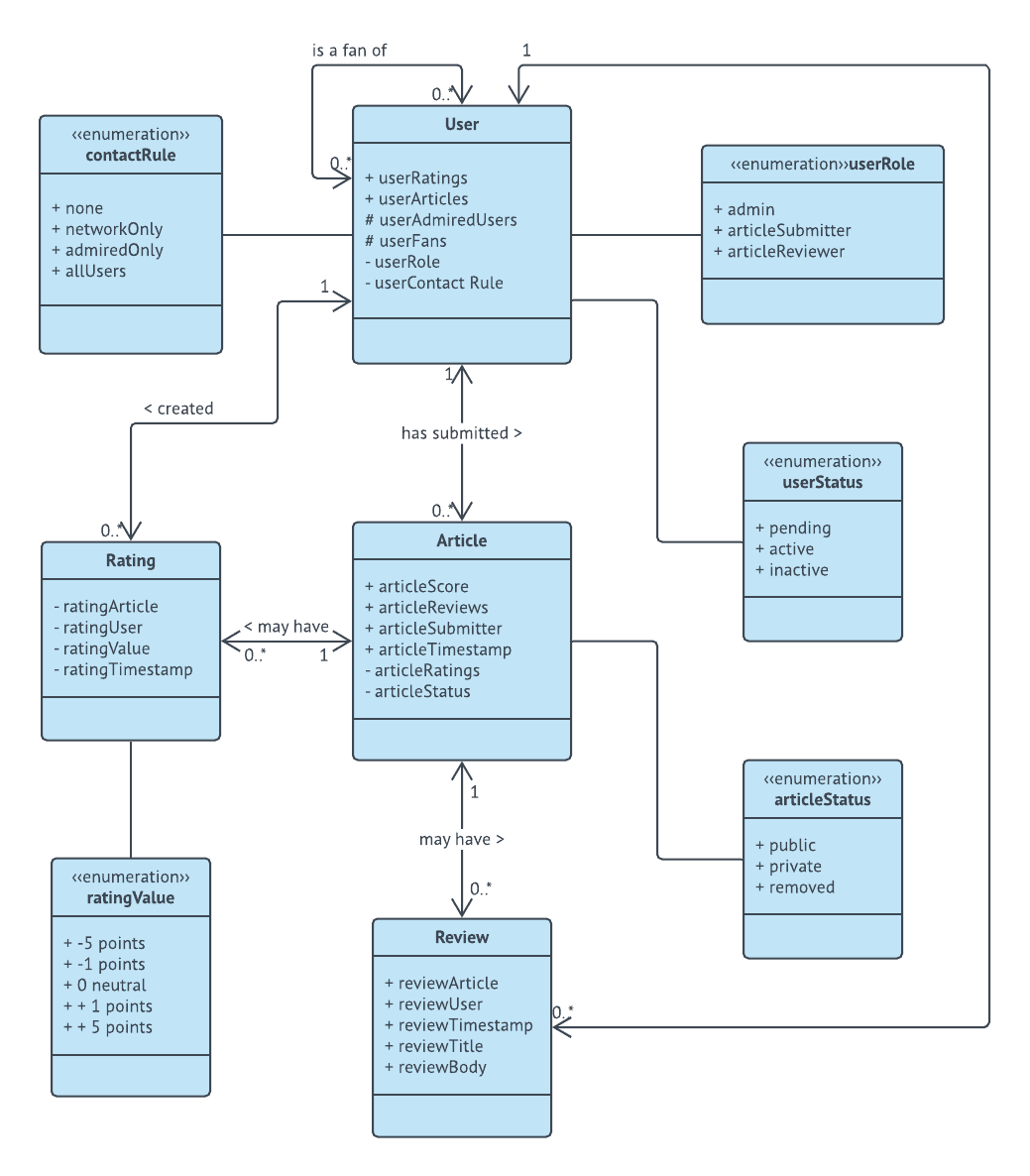
- Class Diagram: The cornerstone of UML, class diagrams depict the classes within a system, their attributes, operations, and relationships. They provide a comprehensive overview of the system’s static structure.
- Object Diagram: Object diagrams are snapshots of a system at a specific point in time, showcasing the instances of classes and their relationships. They are particularly useful for understanding the dynamic behavior of the system.
- Component Diagram: Component diagrams focus on the physical components of a system, such as executables, libraries, and databases, and their dependencies.
- Deployment Diagram: Deployment diagrams illustrate the physical deployment of software components on hardware nodes, providing a clear picture of the system’s infrastructure.
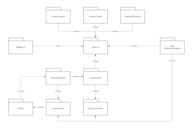
- Package Diagram: Package diagrams represent the organization of elements within a system, grouping related classes and components into logical packages.
2. Behavioral Diagrams:
- Use Case Diagram: Use case diagrams depict the interactions between users and the system, showcasing the functionality provided by the system from a user’s perspective.
- Sequence Diagram: Sequence diagrams illustrate the interactions between objects over time, focusing on the order of messages exchanged between them.
- Collaboration Diagram: Collaboration diagrams, similar to sequence diagrams, depict the interactions between objects but emphasize the relationships between them rather than the chronological order.
- State Machine Diagram: State machine diagrams model the different states an object can assume and the transitions between these states, providing insights into the dynamic behavior of the object.
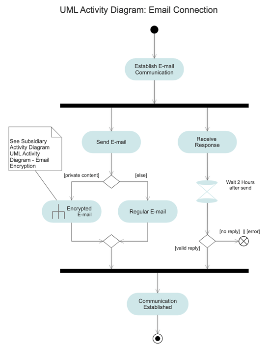
- Activity Diagram: Activity diagrams visualize the flow of activities within a system, highlighting the steps involved in a particular process.
The Power of UML Diagrams in Action: Real-World Applications
UML diagrams find extensive applications across various software development domains, proving their versatility and value:
- Software Design and Development: UML diagrams serve as a foundation for software design, enabling developers to model the system’s architecture, identify key components, and define their interactions.
- Requirement Gathering and Analysis: UML diagrams facilitate the elicitation and documentation of system requirements, ensuring that all stakeholders are aligned on the system’s intended functionality.
- Code Generation and Reverse Engineering: Some UML tools can generate code from UML diagrams, streamlining the development process. Conversely, reverse engineering tools can generate UML diagrams from existing code, aiding in understanding and refactoring legacy systems.
- Database Design: UML diagrams, particularly class diagrams, are widely used in database design to model data structures, relationships, and constraints.
- System Integration and Testing: UML diagrams provide a clear understanding of system interfaces, facilitating integration and testing efforts.
FAQs about UML Diagrams: Addressing Common Queries
1. What are the benefits of using UML diagrams?
UML diagrams offer numerous benefits, including improved communication, early error detection, enhanced maintainability, and reduced development time and cost. They provide a shared language for developers and stakeholders, facilitating collaboration and ensuring a common understanding of the system.
2. Are UML diagrams mandatory for software development?
While UML diagrams are not strictly mandatory, their use is highly recommended, especially for complex projects. They provide a structured and standardized approach to software development, reducing the risk of errors and ensuring clarity throughout the project lifecycle.
3. How can I learn to use UML diagrams effectively?
There are numerous resources available for learning UML, including online courses, tutorials, and books. Familiarizing yourself with the basic concepts and diagram types is essential for effective utilization.
4. What are the limitations of UML diagrams?
UML diagrams can be complex and time-consuming to create, especially for large and intricate systems. They may also require specialized tools and software. It is crucial to use UML judiciously and adapt its application based on the specific project requirements.
5. What are some popular UML modeling tools?
Several popular UML modeling tools are available, including:
- StarUML: A free and open-source UML tool offering a wide range of features.
- Visual Paradigm: A comprehensive modeling tool with both free and paid versions.
- Lucidchart: A cloud-based diagramming tool that offers a user-friendly interface and integration with other tools.
- Enterprise Architect: A professional UML tool with advanced features for enterprise-level projects.
Tips for Effective UML Diagram Creation: Best Practices for Success
- Keep it Simple and Clear: Avoid overwhelming diagrams with excessive detail. Focus on presenting the essential information in a concise and understandable manner.
- Use Standard Notation: Adhere to the standard UML notation to ensure consistency and clarity.
- Focus on the User’s Perspective: Use case diagrams are particularly useful for capturing user requirements and understanding the system from a user’s point of view.
- Iterate and Refine: UML diagrams are not set in stone. Embrace iteration and refinement as the project progresses, ensuring that the diagrams accurately reflect the evolving system design.
- Collaborate and Communicate: Encourage collaboration and communication among team members, using UML diagrams as a shared language for discussion and feedback.
Conclusion: Embracing the Power of Visual Communication in Software Development
UML diagrams have revolutionized software development, providing a standardized visual language for capturing, communicating, and understanding complex system designs. By leveraging the power of these diagrams, developers can streamline communication, facilitate collaboration, and ultimately enhance the quality and efficiency of software development.
From capturing user requirements to modeling system architecture, UML diagrams offer a versatile and powerful tool for navigating the intricate landscape of software development. By embracing these diagrams and incorporating them into their development processes, teams can foster a shared understanding, reduce errors, and ultimately deliver software solutions that meet the needs of their users.


Closure
Thus, we hope this article has provided valuable insights into Unveiling the Power of UML Diagrams: A Comprehensive Guide to Visualizing Software Systems. We hope you find this article informative and beneficial. See you in our next article!